Rlc Band Reject Filter Phase Diagram Electronic Filters Expl
Create band-pass and band-reject filters with rlc series circuits Electronic filters explained-high pass, low pass, band pass, band Solved consider the rlc band reject filter in (figure 1).
Solved Figure 1. RLC-circuit band pass filter R= 1 ohm, L= | Chegg.com
Solved consider a parallel rlc bandreject filter with center Solved rlc function generator experiment filters transcribed problem text been show has Solved item 5 consider the rlc band reject filter in (figure
Band reject filter circuit
Active band reject filters selection guide: types, featuresSolved 4- ( 15 points) a) design a passive rlc band-reject 16. rlc circuits and filters (chapter 16)Circuits rlc.
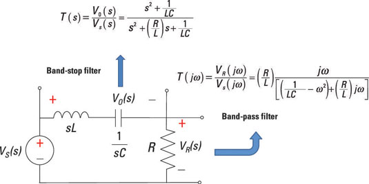
Filter band rlc stop circuit function transfer rejection equation differential passive svg file electrical through circuits laws kirchoff should knowRlc filter circuit diagram Series rlc bandpass filter the circuit in fig. 3Rlc high pass filter.

Solved 1.2 rlc passive filters using the passive rlc
Solved consider the rlc band reject filter in (figure 1).Solved rlc filters experiment 5.2 to function generator Solved 4- ( 15 points ) a) design a passive rlc band-rejectFiltres d'arrêt de bande.
Band stop filter circuit design and applicationsSolved item 5 consider the rlc band reject filter in (figure Solved consider the rlc band reject filter in (figure 1).Passive networks.

Solved fig circuit using rlc series make transcribed problem text been show has
Solved problem #7 vi design an rlc band-reject filter with aSolved using the series rlc circuit in fig. 1, to make a Solved figure 1. rlc-circuit band pass filter r= 1 ohm, l=30+ band stop filter block diagram.
Solved consider the rlc band reject filter in (figure 1).Solved a) design a passive rlc band-reject filter that will Solved consider the rlc band reject filter in (figure 1).Solved design a parallel bandreject rlc filter with f0=4khz.

Band reject filter circuit
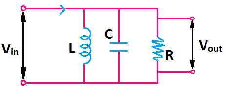
Solved the following is a band-rejection filter fulfilled byCutoff frequency of rlc band pass and band stop filter – valuable tech Create band-pass and band-reject filters with rlc parallel circuitsSolved filter passive rlc transcribed.
Solved . the parameters for a band reject filter rlc seriesFilter active band stop notch reject frequency response filters twin graph information signal circuitstoday conditioners amplifier guide theory detailed general .


